FLEXIBLE PRINTED CIRCUITS
Improving Placement Quality on Flexible Printed Circuits | Introducing Target On Paste (TOP) Placement

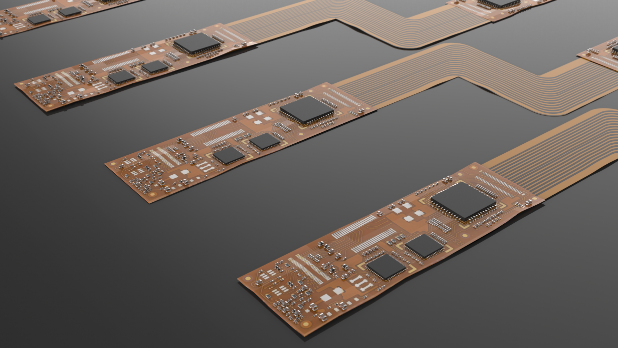
Flexible printed circuits (FPC) are very thin with properties that allow them to be bent to a desired angle for use in electronics with movable parts and interfolded structures, and in three-dimensional wiring in devices with small interior spaces such as smartphones and wearables.
However, while FPC are well-suited to these purposes, it is harder to maintain production quality during SMT processes for these panels. FPC are made from layers of thin, pliable, film-like materials. Polyimide film layers make up most of the material, together with layers of copper foil, and bonding between materials and sputtered layers. All these materials have differing degrees of shrinkage, making FPC prone to warpage and changes in dimensions while used during production. Also, with variances in accuracy for the lamination of materials, the positioning and shape of lands are prone to changing, leading to deviated solder printing and part placement. Normal placement based on CAD data is not adequate for responding to changes in dimensions and changes in positioning per manufacturing lot caused by warpage of materials.
This article presents Fuji’s target on paste (TOP) placement solution that utilizes the effects of self-alignment, and is effective for preventing defective placements on FPC caused by the aforementioned positioning deviations.
Main reasons for deviated positioning when placing on FPC
The land positions do not match the CAD coordinates or Gerber dataThe expansion and contraction of materials causes the land positions to shift, resulting in deviations from the positions designated by the CAD coordinates or the Gerber data.
The reference position is deviated because of changes in the shape for fiducial marks
Part placement positions deviate due to fiducial mark shape changes and mark center position deviations caused by interference from resist and coverlay layers.
The position of the FPC on the carrier board is deviated
The attachment positions on the carrier boards vary because FPC are usually transferred to carrier boards by hand.

Left: Deviation between solder and land due to positional shift
Center: Change in fiducial mark shape caused by interference from resist and coverlay layers
Right: Transfer to carrier board
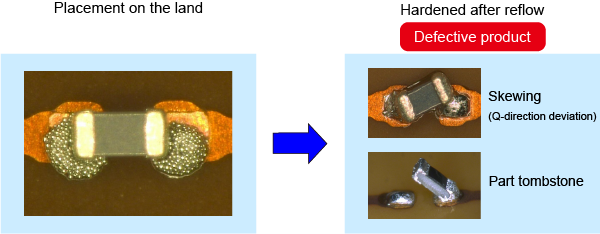
For the reasons given above, the relative positions between lands, solder, and parts deviate, leading to differences in the contact area between part terminals and solder. If parts do not have balanced solder contact, when the solder melts there will be greater pull applied on the part on one side than the other, causing the part to become skewed or tombstoned.

Left: Part placement on deviated solder
Right: Defects resulting from unbalanced pull during reflow
Control placement to prevent defects from deviated placement positions on FPC with TOP placement
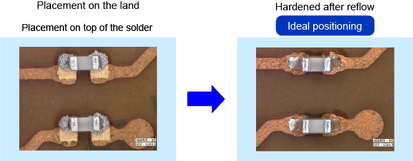
By taking an image of the solder printed on the FPC using the camera in the pick and place machine and using that image to adjust the part placement position, parts can be placed on the center of the solder without needing to be concerned about deviated land positions or deformed fiducial marks. Because the part terminals are contacting an even volume of solder, the self-alignment phenomena is used to maximum effect, for more stable part positioning.
The part is pulled into the correct position on the land by self-alignment
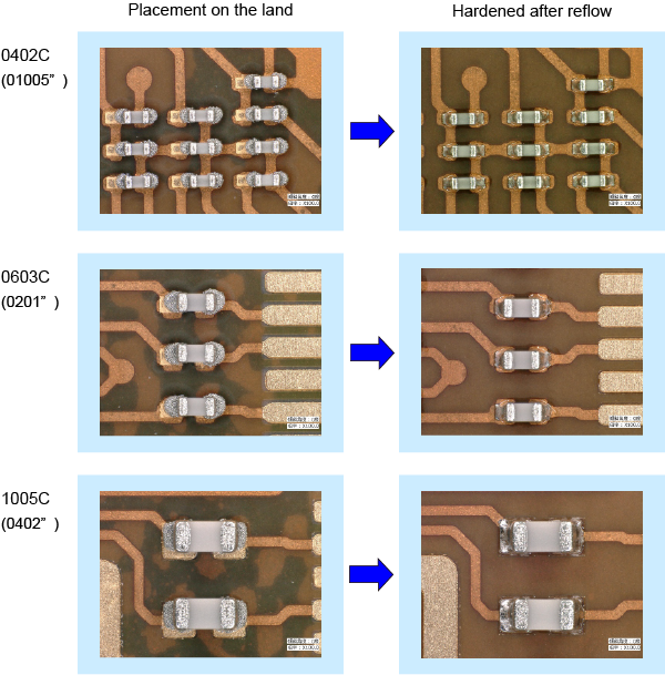
Self-alignment when using TOP placement is very effective for small rectangular chip parts that are 1005 (0402") or smaller, and thus is suitable for the following types of panels.
Panels that use many small chip partsPanels with placements on both sides
Panels that require the use of carrier boards
Placement quality is improved, reducing wasteful disposal and repair work.
Note that there are cases in which the desired result cannot be achieved depending on the state of the panel and the degree of positional deviation.

TOP placement is a solution that is self-contained in the pick and place machine that checks the print position with that machine's camera. Because of this, discrepancies in positional recognition that might arise if vision processing was performed on a different machine cannot occur. This also means that there is no need for replacing periphery units or modifying machines to be able to introduce this solution, keeping the cost of introduction down.