MAINTENANCE
In recent years we have not only seen the smartification of our computers and smart phones, but the devices that surround us as well. And we are seeing more and more of these devices connect to one another across the Internet of Things. As the much anticipated 5G network comes into our communities, the types of parts used to enable 5G technology such as communication module parts are becoming even more prevalent. As parts continue to become even smaller, thinner, and lighter, and electronic circuits are designed to be even closer together with multiple layers, electronic panels are becoming more complex than before. While these products are becoming more complex, how to maintain the same level of quality is an issue. This issue must be tackled from many angles, because while improving functionality and accuracy of equipment is important, the way materials are managed and how maintenance is performed are also contributing factors.
This article will cover three areas that are important to improving quality in SMT processes and maintaining a high level of QCD, "Sure-fire pickup and placement", "Eliminating defective materials", and "Proper maintenance" with supporting data.
- - Sure-fire pickup and placement
- - High-speed, high accuracy placements
- - Detecting pickup stance defects
- - Low impact placement
- - Eliminating defective parts
- - LCR check function
- - 3D coplanarity check
- - Automatic maintenance units
Sure-fire pickup and placement
All the way back in 1985, Fuji became the first manufacturer in the industry to release a pick and place machine that was loaded with a vision processing camera and an independently developed algorithm. This vision processing system greatly enhanced the placement accuracy, and set the new standard in high-accuracy placement technology for increasingly smaller electronic components. For ever advancing and shrinking electronic devices that need to be smaller, thinner, and lighter to be able to deliver more functionality, it is necessary for electrical circuits to be designed at a higher level of complexity for a greater density of parts. Producing high-quality electronic panels under these conditions requires reliable pickup and placement, with both speed and high-accuracy placement, and a way of discovering incorrect pickup stances, while also controlling the impact placed on parts within the SMT processes.
High-speed, high accuracy placements
One of Fuji's core concepts is compact lightweight heads. These heads give Fuji machines an advantage; the small load on the machine during the high-speed movement keeps the vibration down, and the unique servo control technology ensures that high-accuracy placement can be attained. Speed and accuracy are both required for an SMT machine when producing a large quantity of electronic panels in a limited production time. But when working with an XY robot that moves back and forth at high speed, the yawing and pitching that can occur causes variances in the positioning, and the inertia that occurs when the head stops causes the head to shudder. This makes attaining both speed and accuracy not an easy task. At only 2.5 kg, Fuji's small heads are extremely lightweight (approximately 1/3 of the weight of standard heads in the industry). This means that there is very little impact caused by inertia, and with the unique servo control controlling vibrations, it is possible to attain high-speed and high-accuracy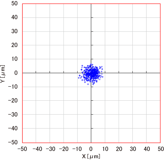
Intelligent parts sensor (IPS)
The intelligent parts sensor (IPS) is a camera that is loaded directly on heads for image recognition. For small parts, the part orientation in the cavity may not be as it should be at pickup due to static electricity generated when the top tape is peeled. This causes pickup errors to occur. There could also be cases in which the part is on the cusp of the permitted tolerance for such a deviation and thus would not be determined as a pickup error. The part would then be placed with that questionable stance. Because Fuji machines check the part stance from both the bottom and from the side, these kinds of poor part stances at pickup are detected. In this way, Fuji is able to raise the quality to single PPM manufacturing quality level.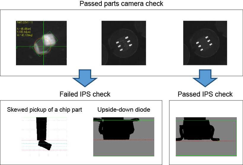
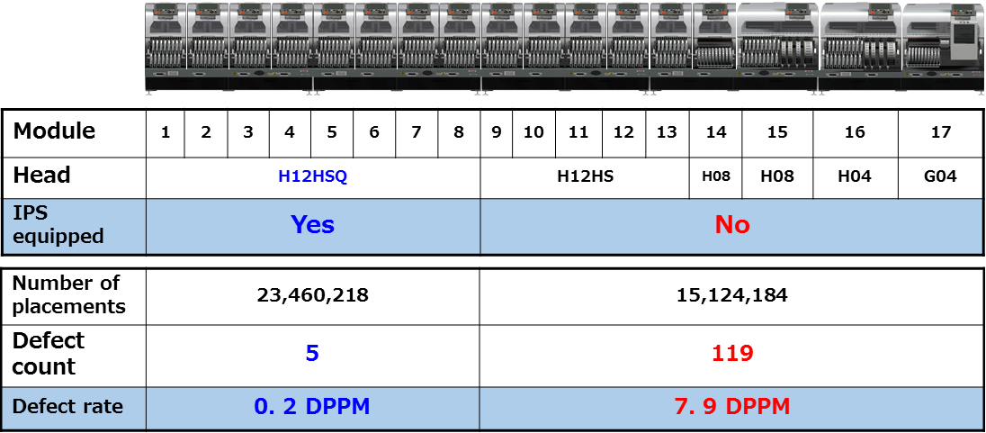
- • High-speed heads: H24S, H24A, V12, H12SQ
- • Multipurpose heads: DX, H08MQ
- • High-accuracy head: G04FQ
Low impact placement
To be able to maintain quality when placing electronic parts that are increasingly smaller, thinner, and lighter, it is necessary to have a high level of stopping accuracy along the X and Y axes, as well as low load on the parts when placing them. Being able to check whether a part will be placed at the correct height and controlling the load on parts during placement is crucial to minimizing the impact on parts, solder, and premounted parts nearby.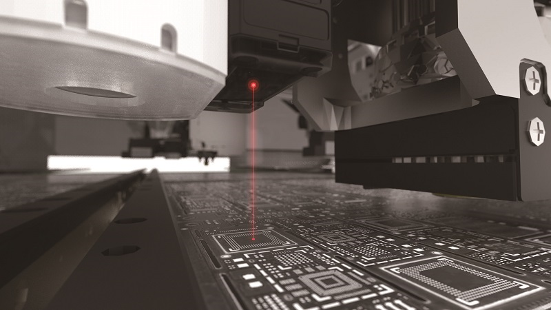
Load control when placing parts
Low impact nozzle
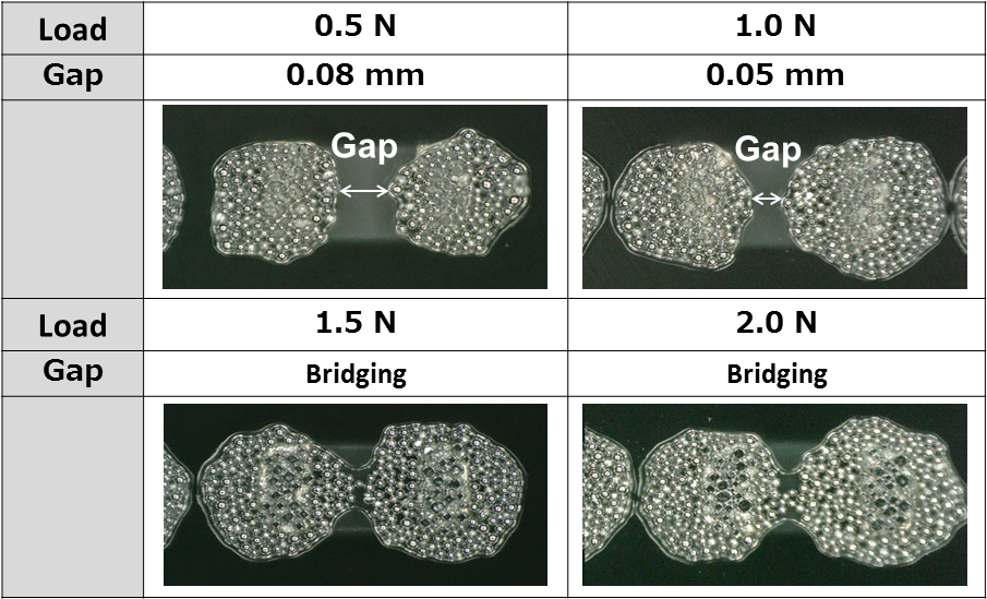
Fuji nozzles are made up of two separate pieces in a way that they are able to absorb the shock of impact during placement. This reduces the load on parts and solder during placement without needing to reduce the placement speed. As electronic panels are trending toward more fine-pitch placements, if a large load is placed on parts and solder during placement the solder may become squashed and spread, causing bridging. Solder bridging causes short circuits and solder balls to form; issues that must be avoided. However it is very hard to tell if this has happened underneath parts in a place that cannot be seen on an inspection machine. On other SMT machines, the mechanism for reducing the load during placement to prevent solder bridging involves reducing the speed at which the nozzle is lowered. Because of the way Fuji nozzles are crafted from two pieces, parts can be placed at a low impact of 0.5 N at top speed, regardless of the size and material of the part. This prevents damage to parts and solder bridging without reducing productivity.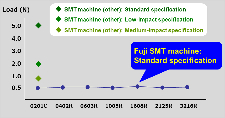
When there are premounted parts and when backup pins cannot be used, there are parts that may fall over or shift at the slightest vibration of the panel, such as odd-shaped connectors that are poorly balanced. These kinds of occurrences can be remedied by lowering the speed at the time of placement. By specifying precisely the point at which the speed is to be lowered and the amount to lower the speed by, the speed can be lowered while keeping the impact on the cycle time to a minimum.
Eliminating defective parts
There are two cases in which a part is considered defective. The first is when human error causes a setting mistake and the wrong part is used, the other is when the part itself is in poor condition. Setting mistakes often occur during part supply rushes when a lot of supply work must be performed all at once. Poor condition of parts tends to be due to external causes such as the method used for storage and how the parts were transported. Connectivity defects caused by misplacements and parts in poor condition can be found during operational testing. But when problems are found after placement that results in corrective work needing to be performed at a later stage. To prevent time-consuming reworking or expensive disposal of product, it is imperative that setting mistakes and parts that are in poor condition are detected before placement.
LCR check function
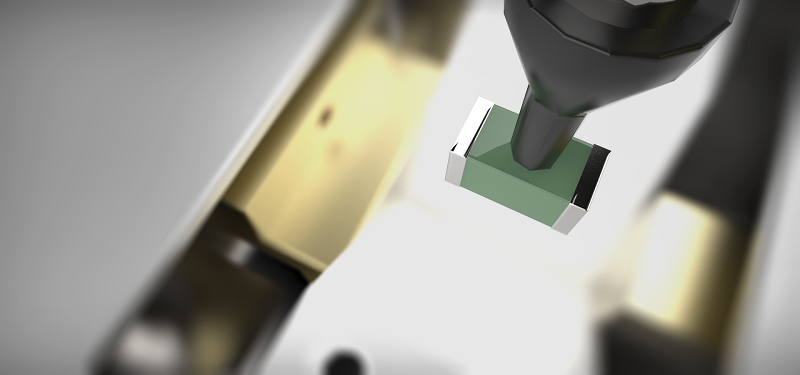
This function is used to check the resistance, inductance, and capacitance of chip parts inside the machine. Because parts are checked inside the machine after the parts are set but before placement is performed, any setting mistakes will be detected.- • When starting and resuming operation
- • When resupplying parts
- • When performing a sampling check (under development)
3D coplanarity check
This detects problems with packages and connector leads, and problems with the bumps on BGAs and CSPs. Because this method even detects problems in the Z direction that are difficult to detect using part imaging cameras, it is possible to prevent the use of parts likely to cause connection issues. Check points- • Lead bending in the Z direction
- • Collapsed bumps
- • Warping of the package body